VMC750 CNC Vertical Machining Center
Features
1. Overall layout of machine tool
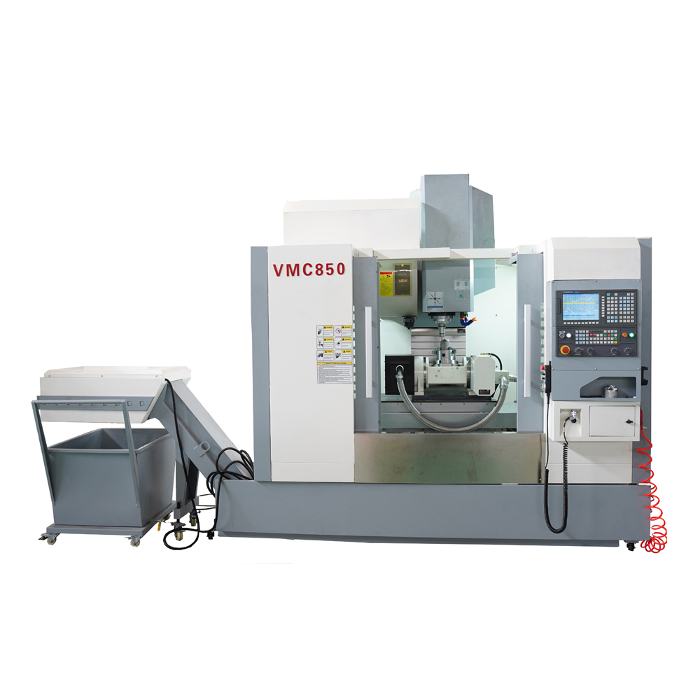
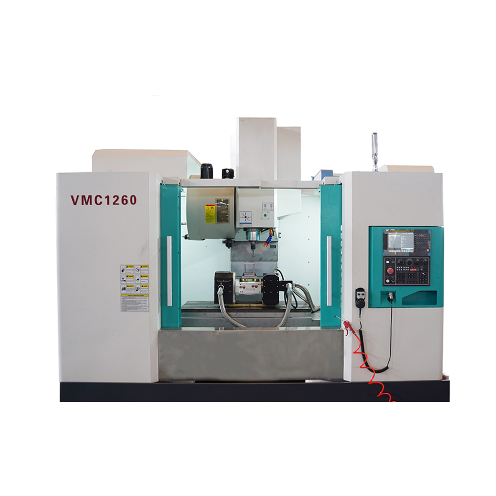
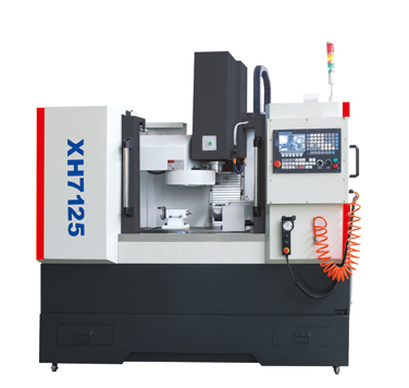
VMC750 vertical machining center adopts vertical frame layout, the column is fixed on the bed, the headstock moves up and down along the column (Z direction), the slide seat moves vertically along the bed (Y direction), and the table moves horizontally along the slide seat (X direction).
Bed, table, slide seat, column, spindle box and other large parts are made of high-strength cast iron material, modeling resin sand process, two aging treatment to eliminate stress. These large parts are optimized by Pro/E and Ansys to improve the rigidity and stability of large parts and the whole machine, and effectively inhibit the deformation and vibration of the machine tool caused by the cutting force.
Note: The XYZ axis consists of two 35-wide roller type wire rails.
2. Drag the system
The three-axis guideway adopts imported rolling linear guideway, which has low static and static friction, high sensitivity, low speed vibration, no crawling at low speed, high positioning accuracy, excellent servo drive performance, and improves the accuracy and precision stability of the machine tool.
The three-axis servo motor is directly connected with the high-precision ball screw through the elastic coupling, reducing the intermediate link, realizing the gashless transmission, flexible feed, accurate positioning, and high transmission precision.
Z-axis servo motor with automatic locking function, in the case of power failure, can automatically lock the motor shaft, so that it can not rotate, play a role in safety protection.
3. Spindle group
The spindle set is manufactured by professional manufacturers in Taiwan, with high precision and high rigidity. The bearings are P4 special bearings for the main shaft. After the whole spindle is assembled under constant temperature conditions, it passes dynamic balance correction and running test, which improves the service life and high reliability of the whole spindle.
The spindle can realize stepless speed regulation within its speed range, and the spindle is controlled by the motor built-in encoder, which can realize the spindle orientation and rigid tapping functions.
4. Knife library
The cutter head is driven and positioned by a roller CAM mechanism during tool change. After the spindle reaches the tool change position, the cutter is returned and sent by the manipulator tool change device (ATC). ATC is a hobbing CAM mechanism, which can run at high speed without noise after preloading, making the tool change process fast and accurate.
5. Cutting cooling system
Equipped with large flow cooling pump and large capacity water tank, fully ensure circulation cooling, cooling pump power: 0.48Kw, pressure: 3bar.
The headstock faces are equipped with cooling nozzles, which can be either water-cooled or air-cooled, and can be switched at will, and the cooling process can be controlled by M-code or control panel.
Equipped with cleaning air gun for cleaning machine tools.
6. Pneumatic system
Pneumatic triplets can filter impurities and moisture in the air source to prevent impure gases from damaging and corroding machine parts. The solenoid valve group is controlled by PLC program to ensure that the spindle loosening tool, spindle center blowing, spindle clamping tool, spindle air cooling and other actions can be completed quickly and accurately.
7. Lubrication system
Guide rail and ball screw pair are lubricated with centralized automatic oil lubrication, each node is equipped with quantitative oil separator, and oil is injected to each lubricating part regularly and quantitatively to ensure uniform lubrication of each sliding surface, effectively reducing friction resistance, improving motion accuracy, and ensuring the service life of ball screw pair and guide rail.
8. Machine tool protection
The machine adopts a protective room in line with safety standards, which not only prevents coolant splashing, but also ensures safe operation and pleasant appearance. Each guide rail of the machine tool has a protective cover to prevent chips and coolant from entering the inside of the machine tool, so that the guide rail and ball screw are protected from wear and corrosion.
9. Chip removal system (optional)
The Y-axis split protection structure makes the iron chips generated during the processing fall directly onto the bed, and the large bevel structure inside the bed makes the iron chips slide smoothly to the chain plate of the chain chip removal device at the bottom of the machine tool. The chain plate is driven by the chip removal motor, and the chips are transported to the chip removal car.
The chain-type chip extractor has large conveying capacity, low noise, overload protection device, safe and reliable operation, and can be used for debris and roll chips of various materials. First, the main structure and technical characteristics of the machine tool
Specifications
|
Model |
VMC750 |
Unit |
||||
|
Worktable |
Worktable size |
900×420 |
mm |
|||
| Max. Loading weight |
600 |
kg |
||||
| T slot size |
18×5 |
mm×pc |
||||
|
Processing range |
X axis travel |
750 |
mm |
|||
| Y axis travel |
450 |
mm |
||||
| Z axis travel |
500 |
mm |
||||
| Distance from spindle end face to workbench surface | Max. |
620 |
mm |
|||
| Min . |
120 |
mm |
||||
| Distance from spindle center to guide rail base |
500
|
mm |
||||
|
Spindle |
Taper (7:24) |
BT40 |
|
|||
| Speed |
50~8000 |
r/min |
||||
| Maximum output torque |
48 |
N.m |
||||
| Spindle motor power |
7.5 |
kW |
||||
| Spindle transmission mode |
Timing Belt |
|
||||
|
Tool |
Tool holder model |
MAS403 BT40 |
|
|||
| Pulling nail model |
MAS403 BT40-I |
|
||||
|
Feed |
Quick move | X axis |
24(36) |
m/min |
||
| Y axis |
24(36) |
|||||
| Z axis |
24(36) |
|||||
| Three axis drag motor power (X/Y/Z) |
2.3/2.3/2.8 |
kW |
||||
| Three axis drag motor torque (X/Y/Z) |
10/10/18 |
Nm |
||||
| Feed rate |
1-6000 |
mm/min |
||||
|
Turret |
Tool magazine form |
Mechanical arm (optional with umbrella) |
||||
| Tool selection method |
Bidirectional nearby knife selection |
|||||
| Magazine capacity |
16 umbrella |
pcs |
||||
| Maximum tool length |
300 |
Mm |
||||
| Maximum tool weight |
8 |
Kg |
||||
| Maximum disc diameter | Full Blade |
Φ78 |
Mm |
|||
| Adjacent empty tool |
φ120 |
Mm |
||||
| Tool change time (knife to knife) |
Umbrella 8s |
S |
||||
|
positioning accuracy |
JISB6336-4:2000 |
GB/T18400.4-2010 |
||||
| X axis |
0.016 |
0.016 |
Mm |
|||
| Y axis |
0.012 |
0.012 |
Mm |
|||
| Z axis |
0.012 |
0.012 |
Mm |
|||
|
Repetitive positioning accuracy |
X axis |
0.010 |
0.010 |
Mm |
||
| Y axis |
0.008 |
0.008 |
Mm |
|||
| Z axis |
0.008 |
0.008 |
Mm |
|||
| Machine weight |
3850 |
Kg |
||||
| Total electrical capacity |
20 |
KVA |
||||
| Machine size(LxWxH) |
2520×2250×2300 |
Mm |
||||
