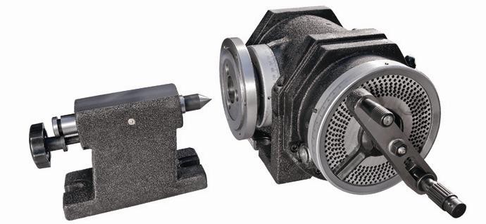
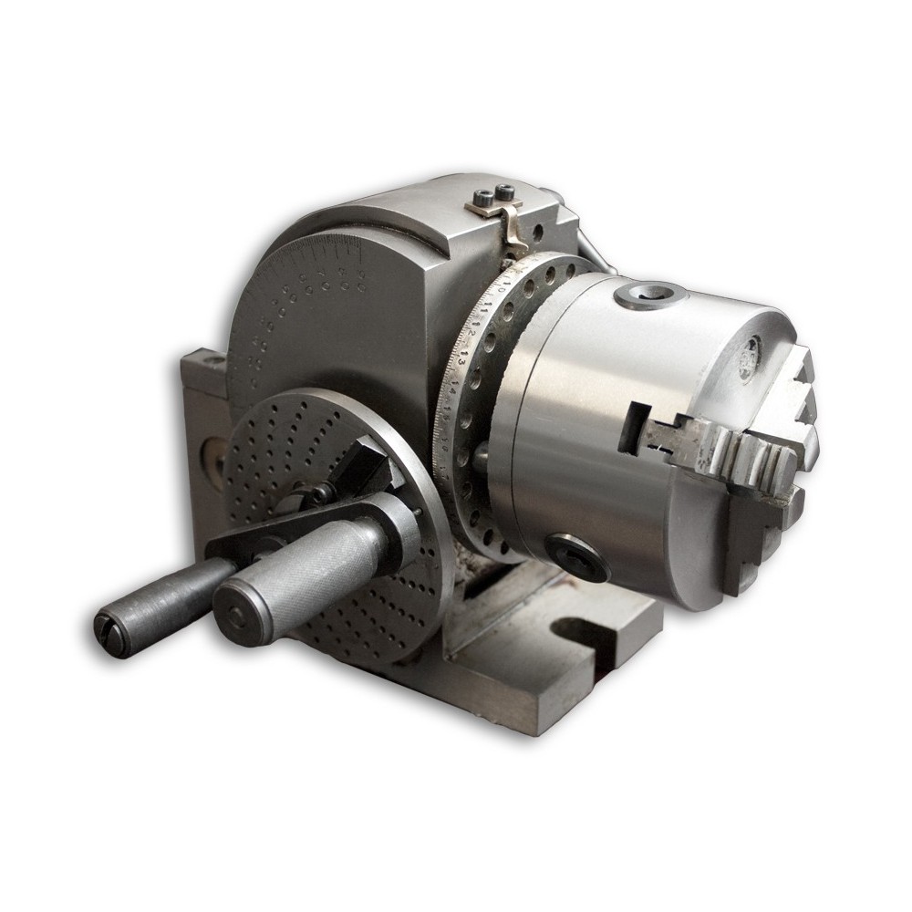
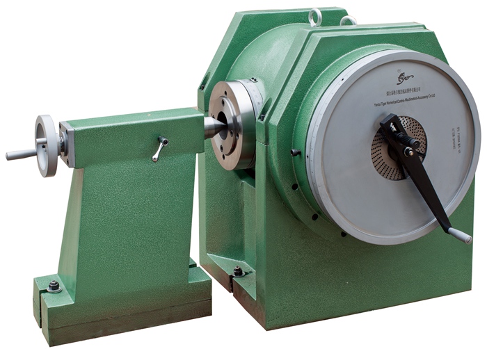
F12 SERIES SEMI-UNIVERSAL DIVIDING HEAD
Features
Type F12 series,the semi-universal dividing head is one of the most important attachment for milling machine.With the help of this dividing head ,the workpiece held can be carried out direct indexing and simple indexing,or rotate to any angle as desired and the periphery of a workpiece can be divided into any divisionsof equal parts and etc.
Specifications
The F12 series with right handwheel.
|
SPECIFICATION |
F12100 |
F12125 |
F12160 |
F12200 |
|
|
Center Height mm |
100 |
125 |
160 |
200 |
|
|
Swivel angle of spindle from it's horizontal position(upward) |
≤95° |
||||
|
Horizontal position(downward) |
≤5° |
||||
|
Rotating angle of spindle for one complete revolution of dividing handle |
9°(540 grad.,1'each) |
||||
|
Min.reading of vernier |
10” |
||||
|
Worm gear ratio |
1:40 |
||||
|
Taper of spindle bore |
MT3 |
MT4 |
|||
|
Width of locating key.mm |
14 |
18 |
|||
|
Diameter of short taper of spindlenose for mounting flange mm |
Φ41.275 |
Φ53.975 |
Φ53.975 |
Φ53.975 |
|
|
Hole numbers on index plate |
1st plate |
24,25,28,30,34,37,38,39,41,42,43 |
|||
|
2nd plate |
46,47,49,51,53,54,57,58,59,62,66 |
||||
|
Individual indexing error of the spindle for one complete revolution of dividing handle |
±45" |
||||
|
Cumulate error at any 1/4 periphery of spindle |
±1" |
||||
|
Max.bearing Kg |
100 |
130 |
130 |
130 |
|
|
Net weight Kg |
57 |
83.5 |
100 |
130 |
|
|
Gross weight Kg |
69 |
96 |
114 |
140 |
|
|
Case Dimensions mm |
610×459×255 |
536×460×310 |
710×505×342 |
710×535×342 |
|
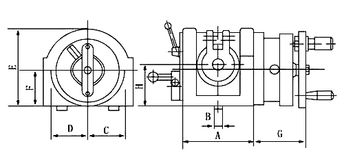
DIMENSIONAL SKETCH
INSTALLATION SKETCH AND DIMENSIONS:
|
Model |
A |
B |
C |
D |
E |
F |
G |
H |
L |
M |
N |
O |
P |
|
F12100 |
162 |
14 |
102 |
87 |
186 |
95 |
116 |
100 |
93 |
54.7 |
30 |
100 |
100 |
|
F12125 |
209 |
18 |
116 |
98 |
224 |
117 |
120 |
125 |
103 |
68.5 |
34.5 |
100 |
125 |
|
F12160 |
209 |
18 |
116 |
98 |
259 |
152 |
120 |
160 |
103 |
68.5 |
34.5 |
100 |
160 |
|
F12200 |
209 |
18 |
116 |
98 |
299 |
192 |
120 |
200 |
103 |
68.5 |
34.5 |
100 |
200 |
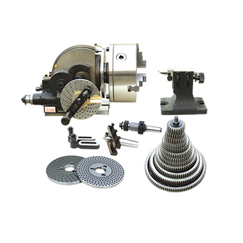
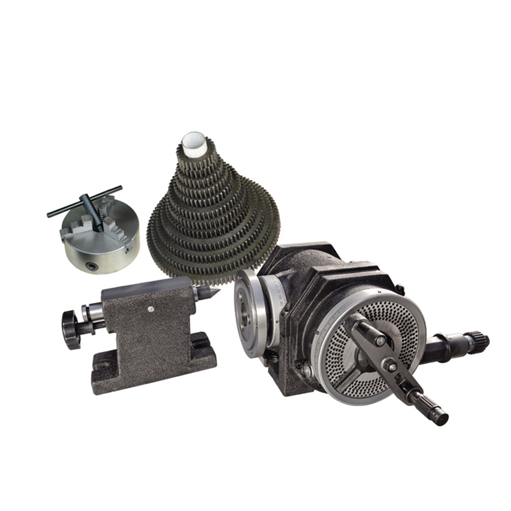
ACCESSORIES:
1.Tailstock 2.Dividing plate 3.Flange 4.3-jaw chuck 5.Round Table(optional)
